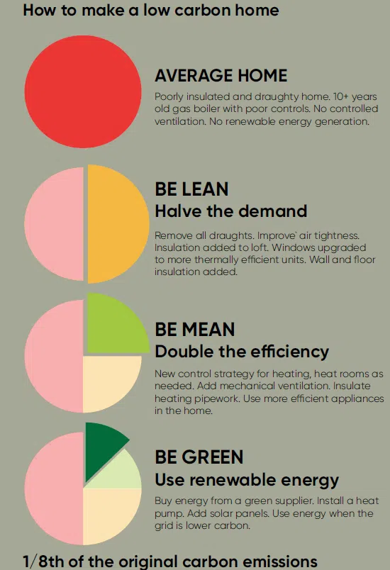
Skip to content

The Devon Retrofit Guide


The Devon Retrofit Guide – Fully Accessible Version (below)

Contents

Introduction – Making Retrofit Routine

Retrofitting offers a practical way for homeowners to improve the comfort and liveability of their homes while reducing their energy use.

The Energy Saving Devon Partnership has produced this guide to support those wishing to carry out their own retrofit upgrades. Our vision is for every home in Devon to be affordable to run, healthy to live in and low carbon, in line with the Devon Carbon Plan.

We have focussed on the four most common housing archetypes in Devon : Victorian granite detached houses, mid-century detached houses, mid-century semi-detached houses and cob houses, offering detailed guidance on how to upgrade these buildings.

Throughout this guide, we explain the retrofitting process, providing you with valuable insights, tips, and practical advice to help you embark on your journey.
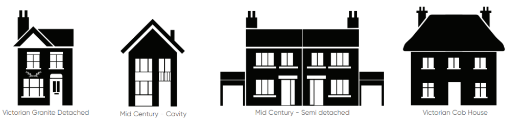
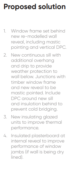
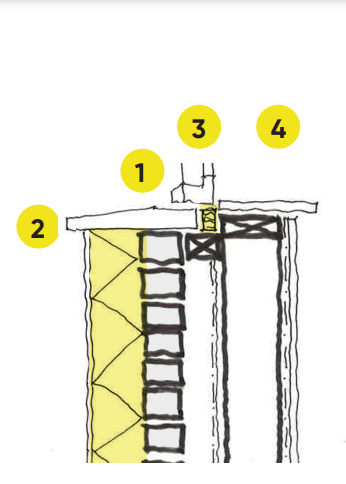
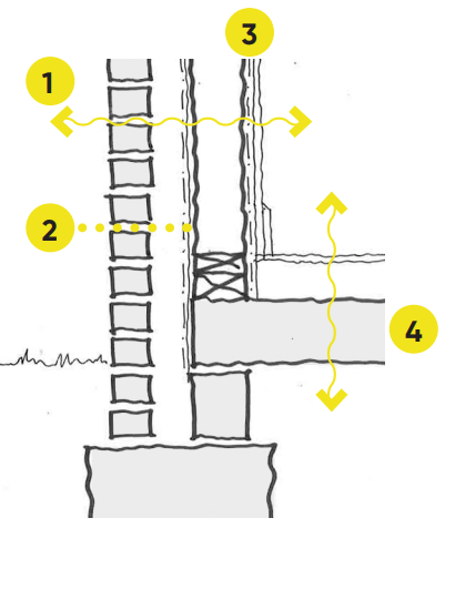
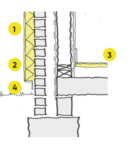
 We hope the information will enable you to understand the benefits of retrofitting and explore the range of clear and actionable energy-saving measures available for your home.

The Devon Retrofit Guide also aims to support smaller building- contractors to advise clients about the appropriate measures available to them to reduce their energy costs and carbon emissions, perhaps as part of other planned renovations.

We hope that you will find this guide useful and wish you well on your retrofit journey.

Energy Saving Devon is delivered by a partnership of all the local authorities in Devon, their strategic partners and local community energy organisations. It is administered by Devon County Council.

Energy Saving Devon logo

0.1 Climate Change

To eliminate carbon emissions from homes, the Devon Carbon Plan promotes insulating them to achieve a 25% reduction in energy demand. Taking this ‘fabric first’ approach will facilitate the installation of heat pumps powered by renewable electricity which, to be affordable to operate, need the building to be thermally efficient.

The Devon Carbon Plan suggests that about 60% of the area’s existing homes will have a heat pump fitted by 2050.

The remaining 40% of properties may not be suitable for heat pumps. This could be due to limited space, close proximity to neighbours, heritage issues or niche construction types. These homes will be switched to a variety of technologies:

•green-hydrogen gas boilers – hydrogen, manufactured using renewable electricity, delivered through the gas network

•hybrid heat pumps – a combination of a heat pump with a gas boiler

•biomass boilers – burning wood pellets or chips

•district heating – homes connected to a network of hot water pipes

•direct electric heating – such as panel heaters or smart storage heaters

This guide focusses on insulating your home, the things you will need to consider to determine if your home is suitable for a heat pump, and how your home can generate renewable electricity.

An infographic showing, from left to right, solar panels, wind turbines, an electrical pylon, a heat pump, and a house with the sun shining down on it. Arrows connect some icons from left to right.

Retrofitting homes is vital to reducing carbon emissions. Almost 25% of Devon’s greenhouse gas emissions come from our homes. It is thought that around 80% of the housing we will occupy in 2050 has already been built.

0.2 Fabric Loss

A house surrounded by text describing where houses lose the most heat and how we can stop it

How much heat does a typical Victorian home lose? Where do we lose the most heat? How can we stop heat loss?

0.3 Fabric Loss (continued)

There are many ways to interpret just how much energy is lost through the building fabric, and each has their own particular use. It is often useful to see how they compare.

Four houses showing how energy is lost by % of energy, kWh per year, kgCO2e and £.

0.4 Energy by End Use

For a typical home, space heating will be the largest consumer of energy. Each element has an important part to play in making a net zero carbon home, but the largest energy consumers are the ones to target first. Most of this guide is focused on how to reduce the energy used for space heating, saving money on energy bills, and improving occupant comfort.

As a home is improved, the other energy uses will become increasingly important, and some can be reduced significantly with little cost or complexity. Replacing lamps with LED equivalents will often pay back within a year, saving energy and carbon, with little disruption. As appliances reach the end of their life, upgrading to new, energy-efficient appliances can make significant energy savings too. For example, changing from a ceramic or halogen electric hob to induction will save on cooking costs, and newer, better insulated fridge- freezers can be considerably more efficient.

A pie chart showing typical end use data for a UK home in 2021. It is broken down into coloured sections showing heating, hot water, appliances, lighting and cooking with corresponding logos.

Typical end use data for a UK home in 2021. Source: Energy Consumption in the UK (ECUK) data from BEIS.

Energy use in a home is also about behaviour and many savings can be made through simple choices and education. Keeping doors closed when it’s cold, switching lights off (and other equipment) when not needed, and turning down the thermostat by a degree, can all make noticeable savings and should be thought of as part of the retrofit process. If a smart meter is not already installed, talk to the energy supplier and get one fitted for free. It can provide live information on how the energy is being used, which can then help inform changes to how the home is used.

1. Energy Use By Element

Introduction To Retrofit Measures and Indicative Energy Savings

1.1 A Low Carbon Home

What is a low carbon home?

There is no one single definition of a low carbon home, but most agree that a low carbon home should:

Minimise energy use

Use a green source of energy

Maximise renewable energy generation

Homes should remain comfortable and still support the residents’ lifestyle, but without excessive usage of energy that is common in the UK housing stock. The amount of energy used in a home can be reduced, and depends on the specific home and how it is used. A low carbon home should aim to use less than 50 kWh/m2/yr in total, around a third of a typical home energy usage.

Homes should also avoid combustion of fossil fuels (gas, oil, or coal), or using wood or biomass burners. Regardless of the energy source, combustion of these fuels release CO2 that would otherwise remain locked away. It will also release pollutants into the atmosphere, predominantly NOx and particulates, that lead to poor air quality within and around the home. Electricity is predicted to be sourced from fully renewable sources in the next 15 years, with cheaper wind and solar power leading the transformation of the national grid. Moving to electric heating for homes through heat pumps will minimise carbon emissions.

Where possible, homeowners should maximise onsite renewable energy generation. For most, this will be led by rooftop mounted solar panels that will generate zero carbon electricity. When the home does not need all the electricity generated, it can be fed back in to the grid and support the electricity grid’s transition to zero carbon.

A series of pie charts showing how to make a low carbon home, resulting in 1/8th of the original carbon emissions.

How to make a low carbon home.

1.2 Improved Windows

Windows are important building elements, bringing daylight in, but also providing views out and a connection to the outside that is so important for our wellbeing. They are often one of the weakest spots for fabric performance in any building, losing more heat through conduction than the walls, and a cause of many draughts.

The first thing to check, even while figuring out the whole retrofit plan, is the seals on any openable windows. Check the closing mechanisms (such as hinges) allow the seals to be properly compressed when closed, reducing any air leakage. If they do not, some hinges can be easily adjusted with a screwdriver, or it may be that new seals will be required. Both can usually be done with minimal DIY knowledge, or can be low-cost for a tradesperson to do.

If the property has single-glazed windows then upgrading to double glazing should be prioritised, assuming there are no heritage concerns. Modern double-glazing can comfortably achieve a U-Value of 1.6 W/m2K, and triple-glazing achieving 0.8 W/m2K, compared to single glazing at around 4.8 W/m2K. Not only will this reduce heat loss by a factor of three, but it will also make the room feel more comfortable, with the inside window surface staying above 15oC even when it is freezing outside (compared to 7oC for single glazing). Triple glazing is excellent if it can be afforded, providing more warmth and longevity, but is not needed for most retrofits.

In properties with existing double glazing, try to establish when the glazing units were installed. This is sometimes printed on the spacer between the glass sheets. Most double glazing will start to de-laminate around 20-25 years after the original install, where the seals between the panes unstick leading to poor thermal performance, and modern glazing is considerably more efficient than even glazing from 5 years ago.

Replacing the glazing units can be done separately to the window frames, but be cautious with uPVC frames as they can be brittle after 25 years, and are easily damaged during replacement.

When replacing the windows, it is important to check they have a suitable trickle vent. This will help to reduce any moisture build-up in the building during occupation, particularly if there is no centralised ventilation system as yet.

For heritage buildings, it may be that secondary glazing can be installed, or in some cases vacuum insulated panels, which are very efficient and can be retrofitted to the original frames.

Diagram showing the heat loss from a window. A red arrow going in shows heat from the sun. Blue arrows going out show heat loss.

Heat gains from the sun can help in winter when we need extra heat, but can lead to significant overheating in summer, especially if the home is well insulated. When thinking of replacement priorities, windows that are more exposed or north facing may be the ones to replace/refurbish first.

1.3 Adding Insulation

Insulation can be added throughout a property, but is particularly important in the following locations:

•Roof/loft space

•Below the floor

•Internal Wall Insulation (IWI)

•Cavity Wall Insulation (CWI)

•External Wall Insulation (EWI)

There are many types of insulation, each with their own specific benefits and limitations, and many need to be used in specific ways to enable them to perform as expected. Understanding their characteristics enables the right insulation to be used for the right task.

Thermal conductivity

A measure of how well the insulation conducts heat, often called the lambda (λ) value, and measured in W/mK. Lower values indicate less heat transfer and therefore a thinner layer of insulation can be used in the construction. Some high-tech insulations can get as low as 0.006 W/ mK, but a majority of insulations are typically around 0.030-0.045 W/mK.

Breathability

Retrofitting using incorrect insulation can cause moisture build-up within the building fabric, which can lead to damp and mould problems. Using breathable insulation can allow moisture to move through the building element (such as a wall, roof, etc.) reducing any condensation issues and is particularly suited to retrofit approaches where the insulation is installed on the warm side of an element, such as internal wall insulation.

A vapour open insulation is where the water vapour can move through the insulation, but the insulation does not regulate the humidity level through absorption. Breathable insulation similarly lets water vapour move through the insulation, but can also ‘store’ some moisture, balancing the humidity level further. Choosing the right insulation level of breathability is best discussed with professionals and the product manufacturers.

Durability

When choosing an insulation, it is important to understand the environment it will be installed within to ensure that it lasts. Key issues are damp, fire, and loading (compressibility).

Damp: Insulating ground floors are a common area where there is a high risk of the insulation getting damp, which will significantly affect the thermal conductivity of some insulations, and some natural insulations will rot. Man- made, closed cell foams, such as polystyrene, will not wick up moisture and tend to be very tolerant of damp.

Fire: There are very few insulations that are designed to be left exposed and a majority will need covering, either by a render or boards, which will reduce the exposure to UV, but will also influence the fire rating of the insulation. We would always advise getting professional advice about the fire performance of an insulation to ensure the correct level of performance.

Load-bearing: In some instances, such as flat roof insulation or below ground insulation, the insulation may be required to be incompressible, carrying the weight of a person or a building. Polystyrenes and foam glass are common insulations used for this purpose.

Other issues: The insulation should be protected against pests, from mice to moths, which can deteriorate the thermal performance. Some insulations will slump if not fully supported when installed.

An infrared thermographic image showing loft insulation that has not been extended to the edge of the roof, letting heat escape.
An infrared thermographic image showing loft insulation that has not been extended to the edge of the roof, letting heat escape
An image of the difference in heat loss between identical homes, but the end house has yet to have cavity wall insulation installed
An image of the difference in heat loss between identical homes, but the end house has yet to have cavity wall insulation installed (source: Jez Wingfield, UCL Energy Institute).

1.4 Types of Insulation

There are a huge array of insulation types, each with their own specific characteristics that should be considered before use. Below is a list of the common types, but this is an emerging market and it is always worth talking to suppliers and manufacturers about their specific product.

Mineral fibres

Includes glass wool, mineral wool and rock wool, and can be formed into rigid panels (called batts) as well as flexible rolls. They tend to have excellent fire resilience and durability, and can allow vapour movement to reduce issues of condensation within the wall (called interstitial condensation). They have moderate thermal performance of around 0.032-0.040 W/mK.

Benefits: Good thermal performance. Available in a variety of forms, rigid batts, flexible rolls, foil-faced, and loose fibres. Vapour open. Very durable.

Watchpoints: Compressible. Not damp tolerant.

Foams

Includes polyurethanes (PIR, PUR) and polystyrenes (EPS and XPS). Can have very low thermal conductivity, 0.020 W/mK for some PIR insulations, and up to 0.037 W/mK for EPS/XPS. They perform poorly in fire tests without careful design, but can be very durable, with XPS and EPS regularly used for ground insulation.

Benefits: Excellent thermal performance. Can form an air-tightness line (see section 1.6).

Watchpoints: Only available in rigid batts. Can shrink over time. Made from oil-based products. Some gases used to create the foam can have very high global warming potential. Non-breathable.

Natural fibres

Includes sheeps wool, wood fibre, cellulose, and hemp/ jute. These tend to have higher thermal conductivity than foams and mineral fibres, from 0.035 W/mK and upwards. Natural fibres are usually vapour-open or breathable, but often need protection from damp and fire.

Benefits: Vapour-open and often truly breathable. Made from renewable materials. Available in a variety of forms, including rigid batts, flexible rolls, loose fibres

Watchpoints: Tend to have poorer thermal conductivity. Can be less durable than man-made alternatives.

Others

Foam glass: Typically made from recycled glass which

is filled with bubbles of air, improving the thermal performance. Available as blocks and a loose aggregate. They are often used in the foundations beneath a home as they are very stable in damp conditions and can be used structurally.

Cork: Available in rigid panels, expanded cork is a breathable insulation able to manage moisture levels in air. Can be mixed with lime plasters to create an insulating plaster for use on walls.

Vacuum insulated panels: Rigid panels of man-made foam insulation, encased in foil with the air removed. Very high performance, but expensive and cannot be cut to shape.

The diagram shows thick layers of insulation in the floor and the roof space, with a thin layer of high-performance insulation on the walls.
The aim for any retrofit should be to create a continuous layer of insulation around the walls, floor and roof. The diagram shows thick layers of insulation in the floor and the roof space, with a thin layer of high-performance insulation on the walls.

1.5 Insulating Walls

Reducing heat loss within the home is possible through retrofitting wall insulation. There are three approaches; internal wall insulation, external wall insulation, and cavity wall insulation. Each approach has benefits and drawbacks, as well as key watch points to be considered before undertaking any work.

In practice, a home can incorporate all three of these approaches, minimising the impact of installation while maximising the thermal efficiency. For example, homes in conservation areas or with complex front façades such as bay windows, may need to install internal wall insulation to the front, but the other walls could be externally insulated.

A home can benefit from wall insulation even if only some of the external walls can be insulated. Flanking walls down the side of a home are often free of pipes and windows and can be readily insulated on the outside, but needs to be considered along with improvement to ventilated floors and lofts. This can be a good first step in improving the thermal efficiency of a home, with minimal disruption.

3 types of insulation are shown, cavity wall insulation, internal wall insulation, external wall insulation. Insulation is highlighted in yellow.

Cavity Wall Insulation (CWI)

Benefits:

Low disruption to install. Does not affect the look of the building.

Drawbacks:

Wall must have been constructed with a formal cavity in the first place. Not as thermally efficient as other methods due to limited dimension of the cavity. Few suitable products available. May need “topping up” in future as the insulation can slump. Will require drilling of approx. 35-50mm holes in the wall to allow insulation to be blown in.

Watch Points:

Walls exposed to driving rain or penetrating damp are at increased risk and likely rely on the formal cavity to remain watertight. These sorts of walls are not good candidates for CWI. Walls with lots of cavity ties or other obstructions may not be good candidates for blown CWI. Walls with lots of informal openings e.g. open cavity to floor voids, vents or windows or doors can be difficult to fill well.

Internal Wall Insulation (IWI)

Benefits:

Maintains external appearance of building. Can help with improving the air tightness of a home when installed throughout. Wide range of insulation materials that can be selected to best suit the wall material and moisture profile of the building envelope. Can provide very good thermal performance.

Drawbacks:

Can be very disruptive, requires the removal of existing wall plaster, repositioning of skirtings, architraves, radiators, power, etc. Requires floor boards to be lifted and the edges of some ceilings to be adjusted. Reduces floor space by moving the line of the wall inward.

Watch Points:

Selection of the right insulation may require professional guidance and possibly detailed assessment. Needs careful thought around floor joists to avoid dampness in timber elements. Careful detailing around external windows and doors to ensure no cold spots. Too much insulation can leave the external wall ‘cold’ and prone to damp which can lead to a risk of freeze-thaw erosion during the colder months. IWI is best suited to projects where the scope and extent of renovation is considering a ‘whole house’ approach.

External Wall Insulation (EWI)

Benefits:

Lower disruption than IWI due to placement on the outside face of the wall. Can have very high thermal performance. Does not affect the internal layout. Can be fitted at lower cost due to fewer steps in the installation process.

Drawbacks:

Changes appearance of the home so should be checked with local planning authority. May require adjustment of other aspects of the building such as the position of the eaves or verge. Requires external mounted services to be removed and re-fixed.

Watch Points:

Details to protect against weathering/rain must be changed to maintain how the building sheds water. Need to coordinate with external pipework, gutters, eaves, etc. and with complex forms such as bay windows and extensions. Existing wall must be dry and in good repair to minimise chance of mould growth in-between the wall and the new insulation. Will require consideration of the landscape around the building to ensure minimal wetting of the wall from splash. Must not bridge Damp Proof Course. Application on semi-detached and terrace houses can lead to difficult detailing at the party wall.

1.6 Air Tightness

All buildings leak some of the warm air from the inside, and colder air can be driven into the building by wind, both of which will increase the heating required for a home. In extreme cases, this can be felt as a draught, causing discomfort. Reducing this uncontrolled air leakage is a robust way of improving home energy efficiency.

Areas that commonly cause leakage are interfaces and joints, where two or more elements in the building envelope meet. The most obvious ones are openings, such as windows and doors, where seals around the openings stop leakage when they are closed. However, the joints between the frames and the walls can also cause significant air leakage, with little infill in the gaps of older buildings, and the fillers in newer buildings shrinking over time. Often, old brickwork can be quite leaky, with old mortar joints between the bricks creating paths for air to move through.

The key to improving air tightness is to create a defined layer in a home that is the air tightness line. This can be a mix of materials, but should form a continuous layer around the envelope of the building with the junctions sealed. The layers can be dedicated air tightness membranes, a polymer-based mortar coat over block work, timber linings, or more typical plasterboard wall linings, but the key is continuity.

When improving the air tightness of a building, it is very important to ensure that adequate ventilation is provided, particularly when additional insulation is added. Often the poor air tightness of a home keeps the internal air quality high, so there needs to be a new method of reducing any humidity build-up once the building fabric is improved. This high humidity associated with poor ventilation can not only damage the building fabric, but also lead to mould growth which may in turn lead to poor health for occupants. While items such as trickle vents in window frames can help, it is strongly recommended that a whole house mechanical ventilation system is integrated.

Illustration of a building cross-section to show the air-tightness. The clear air tight line is represented as an unbroken pink line around the whole house.
A clear air tight line around the whole of the habituated areas of a home is desirable. It can be on the outside of a home, but is more commonly on the inside where it is more protected from the elements.

1.7 Systems

A retrofitted building will likely always need some energy to maintain a comfortable environment, whether for heating or ventilation. A good retrofit will reduce the underlying energy use from a fabric first point of view, but we can also use the energy more efficiently through using better systems. When retrofitting a home, there are two main areas for improving the energy used to maintain a comfortable environment; heating and ventilation.

HEATING

A good boiler will be 90+% efficient, so for every 1 kWh of energy in, it will generate 0.9 kWh of useful heat. Using an Air Source Heat Pump, ASHP, each kWh of electricity used by the ASHP will generate around 3.0 kWh of useful heat. As the electricity grid continues to decarbonise, the energy provided by an ASHP will become nearly zero carbon.

Comparison of a gas boiler (highlighted in orange) and an air source heat pump (highlighted in green).

VENTILATION

In a typical home, fresh air is provided through openable windows, but all of this air needs to be heated back up to room temperature, requiring over 2,000 kWh of energy in a typical home per year.

Instead, using an MVHR could recover as much as 95% of the energy, significantly reducing home energy use, despite the increase in energy to run the fans (a fuller explanation is on page 18).

Diagram showing how a mechanical ventilation with heat recovery (MVHR) is a 95% efficient heat exchanger.

Mechanical Ventilation with Heat Recovery (MVHR).

2. Importance of the interplay between different retrofit measures

2.1 Ventilation / Air Tightness

As a home becomes more air tight and better insulated, the uncontrolled ventilation will reduce and the home will need help to remove stale air and to bring in fresh air. Without adequate ventilation, humidity can build-up, increasing the risk of condensation within the walls. Damp walls will enable mould growth and can lead to serious health problems for occupants.

Usually, the first indicators will be excessive condensation on surfaces, but with internal wall insulation it can be difficult to spot until there is visible mould growth.

New windows with trickle vents will help to avoid this build-up of stale air, but to truly reduce the risk of damp problems a continuous mechanical ventilation system should be installed. There are many different systems, but a Mechanical Ventilation with Heat Recovery (MVHR) unit is encouraged, as this will not only remove stale air and bring in fresh air, but also recover the heat in the exhausted air significantly reducing heating energy. This heat recovery will often substantially offset the additional cost of running the fans.

They can also filter the incoming air helping to remove any allergens.

Kitchens and bathrooms should have some ability to extract, whether through a central system or local fans, whereas occupied spaces such as bedrooms and living rooms should have a fresh air supply. A cascade system can reduce the amount of ducting required, allowing fresh air to be ‘shared’ between these spaces using undercuts to doors to allow the air to move between the rooms.

Any system installed should be able to run at different speeds to enable rapid removal of stale or high humidity air, such as when connected to a bathroom or a kitchen extract, as well as a low background rate. These can be manually controlled or automatic, connected to a humidity sensor in the extract air.

Even when a full MVHR system is installed, openable windows should be included in a retrofitted home. They allow purge ventilation when needed, but also allow the residents to have more control over their space and a simple connection to the outside.

Building cross-section showing the importance of ventilation. Openable windows should be included. Living rooms and bedrooms should have fresh air supplies. Kitchens and bathrooms should have extract systems. Entire occupied volume should be included in ventilation calculations. Passivhaus recommends 0.35 Air Change per Hour (ACH)

2.2 Moisture

It’s all about moisture …

Our homes need to remain structurally sound, free from damp, mould and rot. Regrettably, many existing homes already suffer from excessive cold, damp, mould and condensation. A poorly planned and executed retrofit could actually make this worse. It is very important to understand this risk to mitigate and avoid it.

It may not be obvious, but our homes are constantly dealing with moisture. They are keeping out the rain and stopping the damp rising up from the ground. They are also dealing with the significant amounts of moisture that we generate inside the home from cooking, washing and breathing. Finally, if the building fabric does somehow get wet, it is designed to ensure that it will dry out without long-term damage. Interfere with any of these mechanisms and we could end up doing damage to the health of both the building and its occupants.

Clear principles can address this risk. The risks of retrofit are well understood and can be overcome with sensible design and well-executed construction. Some key rules are:

No insulation without ventilation. As you add insulation you are also likely to increase airtightness. This means less air moving through the building. You can counter this with opening windows and extract fans, but ideally by fitting a whole-house ventilation system like Mechanical Ventilation with Heat Recovery (MVHR).

External insulation is often best. Internal insulation means your external walls become cold and there is therefore a risk of condensation if the warm internal air reaches a cold surface. So, external insulation is preferred, but if internal insulation cannot be avoided, vapour open insulation (such as wood fibre) should be used because it will allow any moisture reaching the cold surface to evaporate, rather than being trapped behind the insulation.

Diagram of vapour flows through 2 types of wall. Brick walls are shown side on with measurements for temperature and distance through wall.

To avoid damp problems we recommend avoiding non-breathable insulation when internally insulating a wall, particularly those with foils or vapour barriers.

3. Guide to Retrofit Planning

3.1 PAS 2035

The Whole House Approach

The importance of a ‘whole house’ approach

Successful retrofit relies on a structured process including adequate assessment, design, installation and monitoring to feed back into future work. These principles, as well as the idea of whole house thinking and the role of retrofit coordinators, have fed into the creation of PAS (Publicly Available Specification) 2035

– the UK’s first retrofit standard. This helps to deliver quality and manage risks associated with retrofit. It aims to ensure clients and homeowners get value for their investment. PAS 2035 follows two core principles:

A ‘fabric first’ approach to reduce the heat demand of a building as much as possible and to ensure newly airtight homes are well ventilated and avoid issues with damp and humidity.

A ‘whole house approach to retrofit’ to ensure retrofit plans for homes consider improvements to the fabric, services and renewable energy generation in a coherent way to minimise both risks and carbon emissions.

Who is a Retrofit Coordinator?

PAS 2035 requires an accredited Retrofit Coordinator to be appointed who will take responsibility for demonstrating compliance with the PAS 2035 standard. This is a relatively new role and different projects require input from different

retrofit specialists depending on the risk category. The Retrofit Coordinator identifies whether the project falls into a low, medium or high-risk category and advises on appropriate steps to minimise risk.

Importantly, many government grants for energy efficiency measures require the PAS 2035 approach to be followed by the project to be eligible for funding.

Graphics illustrate six steps recommended by PAS 2035 for a quality assured retrofit project.

PAS 2035 recommends 6 steps to follow on a quality assured retrofit project. From the Net Zero Carbon Toolkit by Etude, Elementa, PHT, and Levitt Bernstein.

3.2 Heritage and Conservation

Before any planning for retrofit begins, it is important to understand the heritage value of the home, particularly listed status, or homes within conservation areas, but also how the home fits within any local plans.

Always check with the local planning authority to establish what, if any, restrictions apply to the home.

Any works on a building that has some defined heritage status need to be considered with the local planning authority and a heritage consultant. They will be able to assist in determining what needs to be retained, which can then set constraints around the extent of any retrofit activities.

Heritage status will reduce the scale of the retrofit, but there can still be significant energy savings made. Often windows can be refurbished to reduce draughts, internal

wall insulation added, and heat pumps installed, all reducing the heat demand for the building while maintaining the same heritage value.

Specialist heritage groups can provide more detailed advice on how to improve a home that includes heritage features, including: Historic England, Historic Environment Scotland, Society for the Protection of Ancient Buildings (SPAB), and the Sustainable Traditional Buildings Alliance (STBA).

A flow diagram listing four steps to create a heritage retrofit plan.

Creating a heritage retrofit plan.

3.3 Phased Retrofit

To get to net zero carbon, most homes will need to undertake a number of steps as part of the retrofit process. In some cases, these can all be undertaken in one go, however this can be very expensive and

highly disruptive. Instead, a Phased Retrofit should be

undertaken.

LETI, a voluntary organisation that provides industry leading advice on low carbon buildings, released their Retrofit Guide for free. It provides a good overview of the process of a phased retrofit, giving guidance on the planning that is needed.

A key part of establishing the overall process from the beginning is to identify elements that will influence each other, for example ventilation and improvements to air tightness. If setting up the process seems daunting, engage with a Retrofit Coordinator, who will be able to help put together the plan for you. the Energy Saving Devon website can guide you to a local coordinator who will be able to help (link are in section 7) . Mitigating any unintended consequences from the outset can save significant costs later down the line.

When thinking about the retrofit process, think about what other works will be done to the home in that period. For example, loft extensions, boiler replacements, a new kitchen, re-pointing of brickwork, all can be factored into the retrofit plan. Some of these will be ideal times to make another improvement to the efficiency of the home, in some cases making the other works easier to undertake.

The LETI Retrofit Process “wheel”. A grey circle and colour coded arrows show the LETI Retrofit Process in five overall steps, with seven stages in total.

The LETI Retrofit Process “wheel”. Each of the key steps in the retrofit process is shown, but it also shows that some processes will need to be carried out after each retrofit step. Source: LETI Retrofit Guide, 2021

3.4 Retrofit Steps

The retrofit process will include a number of steps of varying complexity. Some of these can be done by DIYers, whereas others need significant experience of building work to achieve the desired result. There are further elements that require input from building professionals, such as where a deep understanding of moisture movement in a wall may be required.

RETROFIT IS A BALANCE OF RISK, COST, AND CARBON REDUCTION. EACH HOME IS DIFFERENT AND THE RETROFIT OPTIONS WILL BE DIFFERENT

A skilled Retrofit Coordinator will be able to advise when you will need to talk to these different levels of external experts.

Home Owner Led

Draft sealing: installation and replacement of draft seals around openings such as windows and doors. Sealing of penetrations through walls with caulk, expanding foam, filler, mortar, or similar.

Window adjustment: repair of hinges to improve closing, ensuring the seals are evenly compressed to reduce drafts.

Window/door refurbishment: repair and reseating of a window/door, including any ironmongery to improve air tightness.

Loft Insulation: laying mineral wool in a loft or to the underside of a roof. Ensuring continuity of insulation across whole roof space.

Contractor Led

PV installation: addition of PVs to roof to be led by an MCS approved contractor*. Installation additional electricity metering and electrical control gear.

Heat pumps: replacement of heating system with heat pumps, including new water tanks and pipework.

Underfloor heating: improve the efficiency of the heating system by using underfloor heating and lowering the heating temperature.

Glazing upgrade: replace glazing units with new double or triple glazing units. Install insulated window frames.

Mechanical ventilation: install continuous mechanical ventilation, associated ductwork, and louvres.

Air tight line: create a continuous air tight line throughout the home using specialist membranes and tapes

*MCS ensure that low-carbon installations are undertaken to the correct standards and provide certification.

Professional Input

Wall insulation: desktop calculation of impact of additional insulation on thermal and moisture considerations for existing wall.

Planning assistance: drawings and evidence required for submission to the local planners to ensure compliance with local requirements.

Heritage impacts: assessment of significance of the building and how to upgrade the building fabric sensitively. Assistance with any planning requirements.

4. Detailed Guidance on Implementation of Retrofit Measures

Strategic Details of Key Junctions per Archetype

Retrofit in detail

There are many ways to improve the energy performance of a dwelling. Each solution will be a response to specific issues and challenges unique to the building in question, however, there are a broad set of principles that can be applied.

This section will examine some of the typical details involved in upgrading the thermal performance of the building envelope.

Of the main housing typologies in Devon we will focus on: Victorian, solid granite wall; detached cavity wall; mid-century semi-detached timber frame; and Victorian Cob. Many of the principles can also be applied to the other dwelling types.

The details will be presented as:

•A typical existing condition, to assist in identification of your building’s current issue.

•Potential upgrades to both the external and internal sides of the external wall.

When considering additional insulation you may be prevented from altering the exterior of the building (for example, by planning or conservation restraints) and so external insulation may not be an option.

You may then have to rely solely on internal insulation and so both options will be explored.

Please note that these details are indicative only, and are based on the common principles of retrofit design.

They may not be applicable to every dwelling but should be considered as a guide to understand principles and terminologies used.

Competent, experienced design professionals should be consulted at all stages.

Simple black and white illustrations of four houses. Houses featured are Victorian Granite Detached, Mid Century - Cavity, Mid Century - Semi detached, and Victorian Cob House.

Assessment principles and terminology

Typical issues and building terms explained

Assessing your building

Assessment is important prior to getting trades involved.

For the purposes of this document, we have focused on four types of typical properties, each of which will have been built in a different way. In general their walls will fall into two categories: solid or cavity.

You can typically tell if your property has a cavity wall by the brickwork. If all the bricks are the same size, laid lengthways, this would indicate you are likely to have a cavity wall.

The thickness of the brick wall may also be indicative. If it is more than 270mm, it is likely to be a cavity wall.

You should seek to target improvements to where they will have most benefit, with the advice of a retrofit assessor key in determining the best options for improvement.

For detached or semi-detached homes the external side walls will typically have fewer obstructions to deal with (downpipes, windows, flues, meter boxes) and so it will be more straightforward to add insulation.

For semi-detached dwellings the shared party wall, which separates each property, will

typically require less treatment as both sides of the wall will be within a heated space.

Be aware of local planning policies, any alterations to the exterior, including the addition of external insulation, may need planning permission.

Be aware of the risks of ‘interstitial condensation’, which can occur when introducing insulation. It is a type of condensation build-up within a wall, roof or floor cavity, and can create moisture issues. Assessment, via inspections and dew point calculations, is vital to ensure the correct retrofit design is applied to mitigate the risk of interstitial condensation.

Many of the following details will therefore note issues of ‘breathability’ i.e. if a wall or roof allows moisture to pass through, or controls it via membranes and ventilated cavities.

Whether you require internal, external or cavity insulation you should ensure that the wall is in good condition and free of any pre-existing damp issues, before carrying out any additional insulating works

Key points to note

Retrofit Assessors, Designers and Installers must do the necessary, and sometimes destructive, investigation work to ascertain the current situation and answer the following:

•How much and of what type of insulation is already present, if any?

•Are there pipes, cables, appliances, flues or other fittings and fixtures that will be in contact with or otherwise be affected by the work?

•What aspects of the work do you need to do together or can be done together to be more efficient?

•How disruptive will the work be? Can you stay in the home during the works?

•What opportunities for refurbishment can be joined up with the works (e.g. a new kitchen)?

Diagram of a typical building section. It shows the rafter, eaves, gutter, rainwater down pipe, window reveal, sill. lintel, floor joist, floor vent, and dwarf wall.

Typical building section.

4.1 Victorian Granite Detached: Roof – Eaves

Insulation applied externally

A list of features of the roof eaves of a Victorian Granite Detached house in typical condition. 1. Roof tiles on battens on roofing felt/membrane. 2. Ventilated roof with insulation at rafter level. Note: some roofs may not be insulated - or lack adequate ventilation path, conditions may vary. 3. Rafter supported on timber wall plate 4. Guttering fixed to timber fascia board 5. Flush timber fascia board protecting rafter 6. Walls absorb moisture in wet weather, which later evaporates in dry weather.
Diagram of a roof showing the typical condition that can be expected and was previously listed.

Typical condition.

Proposed solutions for features of the roof eaves of a Victorian Granite Detached house in typical condition.1. Lower edge of roof to be extended beyond new insulated wall line, including tiles, batten, roofing felt / membrane, fascia board and rainwater goods. 2. New insulation with protective render facing to extend to full height of wall to avoid cold-bridging at roof/wall junction. 3. Reduced-depth extended rafter fixed to existing roof members. 4. Insulation to be provided in plane of ceiling joists. Include proprietary fascia and rafter ventilation tray to ensure necessary airflow within roof void. Additional insulation to be added to loft as required (depending on existing amount) 5. Cold bridge removed

Diagram corresponding to the previously stated points.

Proposed solution.

Key Points to Note

•Eliminating risk of water ingress into fabric of wall is critical. External insulation reduces the ability of the wall to release moisture to atmosphere. This is easier with the uninsulated condition. If existing ceiling is in poor condition, consider incorporation of a Vapour Control Layer (VCL) to any new linings.

Continuity of insulation between wall and ceiling is critical to prevent a cold bridge and the resultant risk of condensation and mould growth.

•Extending the tiles and roofing felt/membrane is essential to ensure weatherproofing.

•A full understanding of the roof ventilation air flow is critical to eliminate the risk of condensation within the roof structure located outside of the thermal line.

4.2 Victorian Granite Detached: Window

Insulation applied externally

A list of features of the windows of a Victorian Granite Detached house in typical condition. 1. Window frame fixed to solid wall. 2. Stone sill with no thermal barrier or damp proof course (DPC) behind – risk of cold bridging, moisture penetration and condensation 3. No vertical DPC or inadequate pointing at vertical window frame (jamb) interface with wall 4. Window likely to be single glazed with very poor thermal performance and presenting significant risk of condensation 5. Timber window frame may be in poor condition due to prolonged exposure to damp solid wall, but should only be replaced where truly defective.

Typical condition.

Diagram corresponding to the previously stated points.
Proposed solutions for the features of the windows of a Victorian Granite Detached house in typical condition. 1. Insulated and rendered external reveal 2. New continuous sill with additional overhang and drip to provide weather protection to wall below. Junctions with timber window frame and new reveal to be mastic pointed. Include DPC around new stone sill and insulation behind to prevent cold bridging. 3. New insulating glazed units to improve thermal performance. 4. Window frame set behind new wall reveal, including vertical DPC and mastic pointing Heat loss reduced

Proposed solution.

Diagram corresponding to the previously stated points.

Key points to note

•Fixing of windows to the uninsulated solid wall presents a risk of a significant cold bridge.

•Insulation plus a DPC to be provided at sill and jambs to reduce cold- bridging and damp penetration .

•If windows / frames are already upgraded and do not need to be replaced then insulated sill covers are available which can be applied over the existing sill, which is another way of removing the cold bridge.

•Heavily weathered sills, which no longer shed water from the wall, could prevent water run-off and increase risk of damp penetration

•Consideration should be given to inclusion of a VCL to internal wall. Mechanical extract to reduce internal moisture should be considered.

4.3  Victorian Granite Detached: Ground Floor

Insulation applied externally

1. Air brick (or similar) to provide sub-floor cross ventilation. There is also likely to be a slate damp proof course (DPC) 2. Timber floorboards on joists supported on wall plates fixed to masonry sleeper walls 3. Heat loss through wall and floor.

Typical condition.

Diagram corresponding to the previously stated points.
1. Ventilation grille fitted within new external wall insulation, to include DPC / flashing to prevent moisture migration from the ground . Insulation to remain 150mm min above external ground level. 2. Insulation to continue below DPC level to minimise cold bridge at base of wall. Ensure insulation is tested for this application. 3. Timber floorboards on new airtight membrane. Path for heat loss minimised. 4. New insulation between floor joists

Proposed solution.

Diagram corresponding to the previously stated points.

Key points to note

•Sleeper walls are often built directly off the ground. Wall plates are sometimes fixed directly to the masonry with no damp proof course separation.

•Construction is therefore susceptible to rising damp – existing timber joists will need to be assessed for any resultant deterioration.

•The sub-floor void requires adequate ventilation to limit the risk of condensation.

•Old air bricks can often be found to have been blocked, or the honeycomb arrangement to sleeper walls (required to permit cross-ventilation) is inadequate or impeded. All to be checked and remedied as required and any sub-floor debris to be removed.

•Any new insulation installed should be kept clear of the ventilation grille to ensure that the void remains well ventilated.

4.4  Victorian Granite Detached: Roof-Eaves

Insulation applied internally

1. Slate/tiles on battens on roofing felt/membrane. 2. Ventilated roof with insulation at rafter level. Note: some roofs may not be insulated - ventilation conditions may vary. 3. Rafter supported on timber wall plate 4. Rainwater goods fixed to timber fascia board 5. Flush timber fascia board protecting rafter 6. Wall resists moisture penetration by shedding bulk water at the surface and by absorbing, storing, and later releasing moisture via evaporation in dry weather.

Typical condition.

Diagram corresponding to the previously stated points.
1. Insulation to be provided in plane of ceiling joists. Replace painted timber fascia fixed to the ends of the rafters and rafter ventilation tray to ensure necessary airflow within roof void. 2. Insulation in ceiling to be continuous with new insulation line on inside of wall. Additional insulation to be added to loft as required (depending on existing amount) 3. Wall to be lined internally with insulation and plasterboard. Path for heat loss removed. 4. Consideration to be given to incorporation of a vapour control layer between the insulation and the plasterboard, especially where vapour closed insulation is used.

Proposed solution.

Diagram corresponding to the previously stated points.

Key points to note

•New internal insulation should ideally be breathable to permit moisture migration through the construction towards the outside.

•Thickness of insulation needs to be considered in relation to the need to permit some of the internal heat energy to get into the solid external wall. This assists in mitigating the risk of interstitial condensation and the gradual increase in moisture within the masonry. U-values of less than 0.4 W/m2K require expert input.

•Continuity of insulation between wall plane and ceiling plane is critical to prevent a cold bridge and the resultant risk of condensation and mould growth.

•A full understanding of the roof ventilation air flow is critical to eliminate the risk of condensation within the roof structure located outside of the thermal line.

4.5 Victorian Granite Detached: Window

Insulation applied internally

1. Window frame fixed to solid wall. 2. Stone sill with no thermal barrier or damp proof course (DPC) behind – risk of cold bridging, moisture penetration and condensation. 3. No vertical DPC or weatherproof pointing at window jamb interface with wall. 4. Window likely to be single glazed with very poor thermal performance and presenting significant risk of condensation. 5. Timber window frame likely to be in poor condition due to prolonged exposure to damp solid wall.

Typical condition.

Diagram corresponding to the previously stated points.
1. Wall to be lined internally with insulation and plasterboard. Consideration to be given to incorporation of a vapour control layer. However other ‘vapour open’ linings can be used. Path for heat loss removed. 2. Window frame set behind new re-modelled wall reveal, including mastic pointing and vertical DPC. 3. Include for at least 20mm of insulation with a facing board at the reveals. 4. New insulating glazed units, or secondary glazing, to improve thermal performance. 5. Include DPC around new stone sill and insulation behind to prevent cold- bridging.

Proposed solution.

Diagram corresponding to the previously stated points.

Key points to note

•New internal insulation should ideally be breathable to permit moisture migration through the construction towards the outside.

•Thickness of insulation needs to be considered in relation to the need to permit some of the internal heat energy to get into the solid external wall. This assists in mitigating the risk of interstitial condensation.

•Heavily weathered sills could prevent water run-off and increase risk of damp penetration.

•Fixing of windows to the uninsulated solid wall presents a risk of a significant cold bridge. Insulation plus a DPC to be provided at sill and jambs to reduce cold-bridging and damp penetration.

•Risk of condensation is accentuated when the wall is colder than other elements. If the whole wall is the same temperature the risk is general – adequate ventilation to remove occupational moisture would be more important than managing the cold bridge, which can be difficult to rectify.

4.6 Victorian Granite Detached: Upper Floor

Insulation applied internally

1. Heat loss through wall. 2. Wall will be warmed from both inside and out to benefit drying. During winter months the heat escaping through the wall helps it dry out and protects it from frost damage. 3. Existing joist embedded within wall.

Typical condition.

Diagram corresponding to the previously stated points.
1. Wall to be lined internally with insulation and wall lining (e.g. plasterboard). Path for heat loss removed. 2. Consideration to be given to incorporation of a vapour control layer (VCL), this will be dependent upon wall lining used. 3. Insulation to extend within joist zone to avoid localised cold-bridging, with expanding tape between insulation and joist. If a VCL forms part of the wall lining then it must be extended through the floor zone too.

Proposed solution.

Diagram corresponding to the previously stated points.

Key Points to Note

•Potential air leakage at pockets in walls for receiving joists could increase risk of interstitial condensation.

•Insulation thickness should be enough to improve heat retention but not so much that it leaves the wall at risk of increased saturation due to so little heat escaping that the drying effect is prevented from occurring. Specialist consultants can carry out an assessment to calculate the risk of adding insulation.

•Thickness of insulation needs to be considered in relation to the need to permit some of the internal heat energy to get into the solid external wall. This assists in mitigating the risk of interstitial condensation.

•VCL and Air Tight Membranes – Membranes must be fitted with care to ensure their edges and junctions are fully sealed. Gaps in membranes will dramatically diminish the value and performance of the assembly and can lead to defects in the building fabric.

•Where vapour membranes are fitted it is good practice to also install mechanical ventilation systems such as MEV or MVHR.

4.7 Victorian Granite Detached: Ground Floor

Insulation applied internally

1.Air brick (or similar) to provide sub-floor cross ventilation. 2. Timber floorboards on joists supported on wall plates fixed to masonry sleeper walls. 3. Heat loss through wall and floor.

Typical condition.

Diagram corresponding to the previously stated points.
1. Wall to be lined internally with insulation and wall lining. 2. Consideration to be given to incorporation of a vapour control layer between the insulation depending on type of wall lining. 3. Timber floorboards on new airtight membrane. Important for air tight membranes to be sealed correctly. 4. New insulation between floor joists to be continuous with wall insulation.

Proposed solution.

Diagram corresponding to the previously stated points.

4.8  Mid-Century Detached: Roof-Eaves

Mid-Century (cavity wall) Detached  – Insulation to cavity

Cavity wall insulation should only be explored where a moisture assessment can confirm that moisture cannot accumulate in the cavity insulation or inner leaf. An alternative would be mechanical extract systems and vapour barriers.

1. Brick outer face to wall, with blockwork inner face and cavity. Heat loss through uninsulated cavity. 3. Slate/tiles on battens on Roofing Felt/membrane. 3. Ventilated roof with insulation at joist level. Note: some roofs may not be insulated - ventilation conditions may vary.

Typical condition.

Diagram corresponding to the previously stated points.
1. Cavity wall insulation, such as beads of foams, injected into existing cavity zone, such as beads or foaming insulations. 2. Pre-existing air flow is maintained, crucial to preventing condensation and rot. 3. Insulation to be provided in plane of ceiling joists. Include proprietary fascia and rafter ventilation to ensure necessary airflow within roof void. 4. Inner lining maintained. Additional insulation can also be applied to the inner or outer walls similar to the solid granite wall section of this guide. 5. To avoid damp and mould issues, increased ventilation should be accompanied by either adequate trickle ventilation, or mechanical ventilation systems.

Proposed solution.

Diagram corresponding to the previously stated points.

Key Points to Note

•Most houses in the mid 1950s were built in 250mm cavity construction with brickwork in both inner and outer parts of the wall, or with brick outer leaf and block inner one. By the 1960s, blockwork was almost universally used for the inner leaf

•For mid-century houses the cavity is likely to be only partially or un-insulated.

•A number of houses subsequently had their cavities filled with polystyrene beads or similar through holes drilled in the external wall. These holes can be used to identify an insulation-filled cavity wall.

•Even with a filled cavity, the maximum level of insulation is limited by the existing depth of the wall so additional insulation to the inner or outer walls should be considered where necessary.

•Three generic types of insulations: Mineral wool, Hollow beads or granules, foamed insulation

•There is a danger moisture will still bridge the cavity when fully filled with insulation. Consultation with experts is always advised when undertaking CWI.

4.9  Mid-Century Detached: Window

Mid-Century (cavity wall) Detached  – Insulation to cavity

Internal wall insulation should only be explored where a moisture assessment can confirm that moisture cannot accumulate in the cavity insulation or inner leaf. Alternatives would be mechanical extract systems and vapour barriers.

1. Window frame fixed to masonry wall with no or limited amount of insulation within cavity. 2. Sill with no thermal barrier or damp proof course (DPC) behind – risk of cold bridging, moisture penetration and condensation. 3. In some cases there may be no vertical DPC or adequate pointing at window jamb interface with wall. 4. Window likely to be single glazed with very poor thermal performance and indow frame fixed to likely to be where condensation occurs.

Typical condition.

Diagram corresponding to the previously stated points.
1. Cavity wall insulation injected into existing cavity zone. Path for heat loss mitigated. 2. Insulated plasterboard at internal reveal to improve performance of window jambs. 3. New insulating glazed units to improve thermal performance. If renewing the window, close the cavity all around with proprietary insulated cavity closers. 4. Include DPC around new sill and insulation behind to prevent cold-bridging. 5. Inner lining maintained. Additional insulation can also be applied to the inner or outer walls. Modifications will be required to the window reveal similar to the solid granite wall section of this guide.

Proposed solution.

Diagram corresponding to the previously stated points.

Key Points to Note

•Cavity wall insulation in suitable situations can be a highly cost effective measure, although there are certain technical risks in using this method to insulate an early cavity wall. The suitability depends mainly on the local exposure to driving rain and the condition of the existing construction.

•As the insulation of the cavity can enhance the thermal performance of a wall without detrimentally affecting its appearance or character this is the preferred alternative wherever the technical risks can be adequately overcome.

•Three generic types of insulations: Mineral wool, Hollow beads or granules, foamed insulation.

•There is a danger moisture will still bridge the cavity when full-fill insulation is added. Consultation with experts is always advised when undertaking CWI.

4.10  Mid-Century Detached: Groundfloor

Mid-Century (cavity wall) Detached  – Insulation to cavity

Internal wall insulation should only be explored where a moisture assessment can confirm that moisture cannot accumulate in the cavity insulation or inner leaf. Alternatives would be mechanical extract systems and vapour barriers.

1. Brick outer face to wall, with blockwork inner face and cavity. Heat loss through uninsulated cavity. 2. Damp proof course (DPC) may be absent or old. Some older DPCs may bridge the cavity in which case the infill insulation may not reach below. 3. Check the condition of your existing solid floor. Insulation was not required before the 1990s so most ground bearing floors are uninsulated.

Typical condition.

Diagram corresponding to the previously stated points.

1. Cavity wall insulation injected into existing cavity zone. Path for heat loss mitigated. 2. Inner lining maintained. Additional insulation can also be applied to the inner or outer walls similar to the solid granite wall section of this guide. 3. Floor finish with underlay. 4. If solid floor is in bad repair, this can be replaced with rigid insulation beneath. Note that door and thresholds may need to be trimmed to suit raised floor level.

Proposed solution.

Diagram corresponding to the previously stated points.

Key Points to Note

•A solid floor can still be insulated even if it doesn’t need replacing. Rigid insulation can be laid on top of the original floor, with floor finish above. This will raise floor level, so modifications to doors and thresholds should be considered.

•Before deciding to fill an empty cavity, check the cavity size and establish whether there is any material within the cavity itself. The type of insulation material used to fill the cavity will be partly determined by the exposure of the wall.

•Three generic types of insulations: mineral wool, hollow beads or granules, foamed insulation

•There is a danger moisture will still bridge the cavity when full-fill insulation is added. Consultation with experts is always advised when undertaking CWI.

•If the ground floor is timber suspended, then follow the guidelines for the Victorian flooring shown earlier.

•Your sub-floor may be suspended with a cavity underneath. This will be evident by ventilation bricks on the lower face of the external wall. In this case the sub- floor will require adequate ventilation to limit the risk of condensation.

4.11  Mid-Century Semi-Detached, Timber Frame: Roof

Insulation applied internally

1. Brick outer face to wall, with timber stud inner face and cavity. Heat loss through uninsulated cavity. 2. Vapour Control Layer (VCL) to inner face of plasterboard lining. 3. Slate/tiles on battens on roofing felt/membrane. 4. Ventilated roof with insulation at joist level. Note: some roofs may not be insulated - ventilation conditions may vary.

Typical condition.

Diagram corresponding to the previously stated points.

1. Insulation to be provided in plane of ceiling joists. Include proprietary fascia and rafter ventilation to ensure necessary airflow within roof void. 2. Insulate by infilling between the studs. Mineral wool must be designed for use on an external wall. 3. Position of VCL to be moved to allow additional insulation to be positioned to inner face of timber frame 4. Internal wall lining. Note that if wall has electrical or mechanical fixings, a small services zone can be created using additional metal framing to allow for conduit, pipework etc.

Proposed solution.

Diagram corresponding to the previously stated points.

Key Points to Note

Insulation materials should be chosen with consideration for their breathability and interaction with the timber frame.

•Insulation should not be installed until the structural timber frame is below 20% moisture content and the building is weather tight, as wet insulation can retain moisture.

•If the timber of a working dwelling has a humidity 20% or greater then it is ‘wet’ and likely suffering from other issues such as rot. The cause could be a defect in the roof, gutters, drains, plumbing etc., but should be identified before any work begins.

•For all of the above details it is recommended that a dew point calculation is undertaken to ensure the correct retrofit measures (depth of insulation etc.) are being employed.

4.12  Mid-Century Semi-Detached, Timber Frame: Window

Insulation applied internally

1. Window frame fixed to masonry wall with no or limited amount of insulation within cavity. 2. Sill with no thermal barrier or damp proof course (DPC) behind – risk of cold bridging, moisture penetration and condensation 3. In some cases there may be no vertical DPC or adequate pointing at window jamb interface with wall. 4. Window likely to be single glazed with very poor thermal performance and likely to be where condensation occurs. 5. Existing timber frame may or may not have insulation and / or a Vapour Control Layer (VCL).

Typical condition.

Diagram corresponding to the previously stated points.

1. Window frame set behind new re-modelled wall reveal, including mastic pointing and vertical DPC. 2. Existing timber frame may or may not have existing insulation. Upgrade or infill between the studs. 3. Position of VCL to be moved to allow additional insulation to be positioned to inner face of timber frame. 4. Internal wall lining. Note that if wall has electrical or mechanical fixings, a small services zone can be created using additional metal framing to allow for conduit, pipework etc.

Proposed solution.

Diagram corresponding to the previously stated points.

Key Points to Note

Insulation materials should be chosen with consideration for their breathability and interaction with the timber frame.

•Windows and doors are usually the weakest point in the insulation envelope, as well as potentially one of the worst areas for thermal bridging.

•Around openings such as windows and doors, stress cracks can appear if the insulation is not installed correctly. In order to mitigate against this, a reinforcing mesh should be applied at the corner angles.

•To achieve good airtight seals around window frames, high quality proprietary airtightness tapes should be used.

4.13  Mid-Century Semi-Detached Timber Frame: Upper Floors

Insulation applied internally

1. Brick external face. Ensure adequate pointing between bricks, essential to prevent water penetrating easily. 2. Cavity with breather membrane to timber structure. Existing timber frame may or may not have insulation and / or a Vapour Control Layer (VCL). 3. Floor joist at upper floor. Check for timber decay within joist end and wall- plate before installing insulation.

Typical condition.

Diagram corresponding to the previously stated points.
1. Wall to be lined internally with insulation and plasterboard. Path for heat loss removed. 2. Existing timber frame may or may not have insulation. Upgrade or infill between the studs. 3. Position of VCL to be moved to allow additional insulation to be positioned to inner face of timber frame. 4. Internal wall lining. Note that if wall has electrical or mechanical fixings, a small services zone can be created using additional metal framing to allow for conduit, pipework etc. 5. Insulation to extend within joist zone to avoid localised cold-bridging, with expanding tape between insulation and joist

Proposed solution.

Diagram corresponding to the previously stated points.

Key Points to Note

Insulation materials should be chosen with consideration for their breathability and interaction with the timber frame.

•Potential air leakage at pockets in walls for receiving joist could increase risk of interstitial condensation.

•Thickness of insulation needs to be considered in relation to the need to permit some of the internal heat energy to get into the solid external wall. This assists in mitigating the risk of interstitial condensation.

4.14  Mid-Century Semi-Detached, Timber Frame: Ground floor

Insulation applied internally

1. Brick outer face to wall, with timber stud frame and cavity. Existing timber frame may or may not have insulation and / or a Vapour Control Layer (VCL). 2. Heat loss through uninsulated cavity. 3. Damp proof course (DPC) may be absent or old. Some older DPCs may bridge the cavity in which case the infill insulation may not reach below. 4. VCL to inner face of plasterboard lining. 5. Ceck the condition of your existing floor. Unless rigid insulation has been used, which can be fitted either above or below the concrete, then there will be a cold bridge to the ground.

Typical condition.

Diagram corresponding to the previously stated points.
1. Upgrade or infill between the studs 2. Wall to be lined internally with insulation and plasterboard. Path for heat loss removed. 3. Position of VCL to be moved to allow additional insulation to be positioned to inner face of timber frame. 4. Internal wall lining. Note that if wall has electrical or mechanical fixings, a small services zone can be created using additional metal framing to allow for conduit, pipework etc. 5. If solid floor is in bad repair, this can be replaced with rigid insulation beneath. Change to the floor level may require adjustment to doorways and stairs

Proposed solution.

Diagram corresponding to the previously stated points.

Key Points to Note

Insulation materials should be chosen with consideration for their breathability and interaction with the timber frame.

•Your sub-floor may be suspended with a cavity underneath. This will be evident by ventilation bricks on the lower face of the external wall. In this case the sub-floor will require adequate ventilation to limit the risk of condensation.

•A solid floor can still be insulated even if it doesn’t need replacing. Rigid insulation can be laid on top of the original floor, with floor finish above. This will raise floor level, so modifications to doors and thresholds should considered.

•If the ground floor is timber suspended, then follow the guidelines for the Victorian flooring shown earlier.

4.15  Mid-Century Semi-Detached, Timber Frame: Roof

External Wall Insulation

1. Brick outer face to wall, with timber stud inner face and cavity. Heat loss through uninsulated cavity. 2. Vapour Control Layer (VCL) to inner face of plasterboard lining. 3. Slate/tiles on battens on roofing felt/membrane. 4. Ventilated roof with insulation at joist level. Note: some roofs may not be insulated - ventilation conditions may vary.

Typical condition.

Diagram corresponding to the previously stated points.
1. Insulation to be provided in plane of ceiling joists. Include proprietary fascia and rafter ventilation to ensure necessary airflow within roof void. Maintain clear vent path. 2. Existing timber frame may or may not have insulation. Upgrade or infill between the studs. 3. New insulation with protective render facing to extend to full height of wall to avoid cold-bridging at roof/wall junction. Insulation to be positioned to ensure ventilation route maintained. Alternatively line of eaves could be pushed out. 4. Existing inner wall lining maintained.

Proposed solution.

Diagram corresponding to the previously stated points.

Key Points to Note

Insulation materials should be chosen with consideration for their breathability and interaction with the timber frame.

•Insulation should not be installed until the structural timber frame is below 20% moisture content and the building is weather tight, as wet insulation can retain moisture.

•For all of the above details it is recommended that a dew point calculation is undertaken to ensure the correct retrofit measures (depth of insulation etc.) are being employed.

•The Victorian granite detached detail shown earlier includes a detail for an extended eave.

4.16  Mid-Century Semi-Detached, Timber Frame: Window

External Wall Insulation

1. Window frame fixed to masonry wall with no or limited amount of insulation within cavity. 2. Sill with no thermal barrier or damp proof course behind – risk of cold bridging, moisture penetration and condensation. 3. In some cases there may be no vertical damp proof course (DPC) or adequate pointing at window jamb interface with wall. 4. Window likely to be single glazed with very poor thermal performance and likely to be where condensation occurs.

Typical condition.

Diagram corresponding to the previously stated points.

1. Window frame set behind new re-modelled wall reveal, including mastic pointing and vertical DPC. 2. New continuous sill with additional overhang and drip to provide weather protection to wall below. Junctions with timber window frame and new reveal to be mastic pointed. Include DPC around new sill and insulation behind to prevent cold bridging. 3. New insulating glazed units to improve thermal performance. 4. Insulated plasterboard at internal reveal to improve performance of window jambs (if wall is being dry lined).

Proposed solution.

Diagram corresponding to the previously stated points.

Key Points to Note

•Around openings such as windows and doors, stress cracks can appear if the insulation is not installed correctly. In order to mitigate against this, a reinforcing mesh should be applied at the corner angles.

•Water penetration is possible through poorly maintained sills, allowing moisture build up within wall and timber structure.

•If window / frame is already upgraded and does not need to be replaced, then insulated sill covers are available which can be applied over the existing sill, providing another method of removing the cold bridge.

4.17  Mid-Century Semi-Detached, Timber Frame: Ground floor

External Wall Insulation

1. Brick outer face to wall, with timber stud frame and cavity. Heat loss through uninsulated cavity. 2. Damp proof course (DPC) may be absent or old. Some older DPCs may bridge the cavity in which case the infill insulation my not reach below. 3. Vapour Control Layer (VCL) to inner face of plasterboard lining. 4. Check the condition of your existing solid floor. Unless rigid insulation has been used, which can be fitted either above or below the concrete, then there will be a cold bridge to the ground.

Typical condition.

Diagram corresponding to the previously stated points.
1. New insulation with protective render facing. 2. Note that allowance will need to be made for modification to external services fixed to wall, downpipes, flues etc. Min 150mm from ground. 3. Floor finish with underlay. 4. Insulation finishes above ground level with sufficient clearance to avoid wicking of moisture from the ground and splashing of rain compromising the insulation effectiveness.

Proposed solution.

Diagram corresponding to the previously stated points.

Key Points to Note

•Your sub-floor may be suspended with a cavity underneath. This will be evident by ventilation bricks on the lower face of the external wall. In this case the sub-floor will require adequate ventilation to limit the risk of condensation.

•If the ground floor is timber suspended, then follow the guidelines for the Victorian flooring shown earlier.

4.18  Cob: Wall & Eaves

Insulation applied internally – only where appropriate

The thermal performance of a dry cob wall, free of serious defects can be as good as a modern built house or even better.

1. All existing walls of any construction and material need to be in good repair prior to works. 2. The properties of a cob wall make it difficult to add insulation due to vapour issues, however, breathable cork insulated plaster can be applied to the inner face for a modest upgrade in performance. 3. It is possible for insulated plaster to be added inside or out but adding to the outer face should only be considered where there are other benefits like protection and consolidation of the cob itself.

Typical cob wall.

Diagram corresponding to the previously stated points.
1. Thatch retained. 2. Permeable insulation to span below rafters. 3. New lime plaster ceiling. 1. Thatch retained. 2. Permeable insulation. 3. Lath and plaster ceiling retained. 4. Continuous ventilation air gap with insect mesh to allow ventilation path to be maintained.

Insulation options.

Diagram corresponding to the previously stated points.

Key Points to Note

•Many thatched buildings have rooms within the roof space, consequently insulation will often have to be placed beneath the sloping rafters in these rooms. This can be achieved in different ways depending on the existing conditions.

•Whenever it is proposed to add extra insulation immediately below a

thatched roof covering, particularly if there is to be no ventilated space under the thatch, it is recommended that expert advice be taken on the risk of increasing condensation occurring within the build-up of the roof covering.

•Although small amounts of condensation can be briefly tolerated in a permeable form of construction, persistent moisture within these materials can be very damaging.

5. Detailed Guidance on Implementation of Retrofit Measures: Services

5.1  Mechanical Ventilation

Continuous ventilation through a mechanical system is a relatively new concept in the UK, but is a key element to reduce problems with damp and keep the air fresh. It is the continuous running of these systems that keeps the air fresh, ensuring that there is no build up of pollutants or humidity, keeping the air quality high. All systems should be supplemented with openable windows where possible, providing purge ventilation when needed, but also more control for residents over their environment.

When improving the air tightness of a building and/or improving the thermal performance of the fabric, it is very important to add ventilation to the home to reduce the likelihood of mould growth and negative health impacts that they can bring.

Mechanical Extract Ventilation, MEV

An MEV system consists of a single fan unit, typically mounted in a loft space, which pulls air from within the house and expels it out of the house, usually through a vent in the roof. Fresh air is pulled into the home through trickle vents in windows, gaps in the building fabric, and any open windows. If the home has been made air tight, then these systems may struggle without specific openings to bring in fresh air. It is important that any fresh air openings do not lead to drafts and discomfort for the residents.

A diagram showing the cross section of a house. Arrows show the path of air: it enters through openings in the building fabric, is pulled in by an MEV system in the loft and then is pushed outside.
An MEV is typically located in the loft, but can be located anywhere in the home. Ducts connect the unit to the rooms that require extract, and fresh air is pulled in through openings in the building fabric.

Benefits: Relatively easy to install as only one set of ductwork required. Can help with internal rooms such as WCs that may need extract. Cheaper to buy than MVHR.

Drawbacks: Requires fresh air openings to be always open. Does not recover heat from the extracted air. Still requires some ductwork to connect rooms. Difficult to control how much fresh air each room gets, and where it is delivered. No way of filtering fresh air.

Watchpoints: Air paths from each room to each extract point are required, so doors may need an undercut gap to allow the air to move between rooms. Trickle vents in windows may be enough to provide fresh air, but will need to be checked by the installer. Need to ensure that fresh air openings do not lead to drafts and discomfort

Mechanical Ventilation

Positive Input Ventilation, PIV

Similar to an MEV, a PIV is a single fan that pushes air into the home, usually located in the loft where the air is typically warmer than outside, but can be wall mounted. By pushing the fresh air into the home, the stale air is exhausted out of the home through trickle vents, gaps in the building fabric and any open windows. These do not require ducting between the unit and the rooms, and the air supply can be preheated to improve comfort.

A diagram showing the cross section of a house. Arrows show the path of air: it is pulled in through vents in the rood and pushed into the rest of the home by a PIV.
A PIV is located in the loft of a home, pulling in fresh air through the vents in the roof and pushing it into the rest of the home. The stale air is then pushed out of openings within the walls and windows.

Benefits: Very easy to install with no ductwork required. Incoming air can be filtered to reduce pollutants including pollen. Air can be preheated to improve the comfort in the home.

Drawbacks: Requires exhaust openings to be always open. May still need local intermittent extract for bathrooms, kitchens, etc. Does not recover heat from exhausted air. Can be more expensive to run than MEV due to pre-heating of incoming air. Difficult to control how much fresh air each room gets, and where it is delivered.

Watchpoints: If installed in the loft, need to ensure a good airtight loft installation to prevent short-circuiting the air path straight back to the fan. Air paths between the fan and each room are required, so doors may need an undercut gap to allow air movement between rooms. Filters will need to be changed regularly, typically every 3-6 months to ensure efficient operation.

5.2  MVHR

Mechanical Ventilation with Heat Recovery, MVHR, units have been around in some form for over 40 years, and are a well tested technology in Northern Europe. They supply fresh air and extract stale air at the time, with a heat exchanger within the unit recovering the heat from the extracted air and warming the incoming air. This can significantly reduce heat loss through ventilation, as that fresh air will already be much closer to room temperature and will not need as much additional heating as natural ventilation, MEVs, or PIVs. It will also reduce the chance of cold drafts that can lead to discomfort.

The MVHR unit will be connected to ducts that will need to run throughout the home, with extracts typically in areas of higher humidity such as kitchens and bathrooms, and supply ducts running to occupied areas including bedrooms and living rooms. To reduce the amount of ductwork, it is common to use cascade ventilation, where the fresh air is supplied to these occupied areas, and extracted in the high humidity spaces, passing through door undercuts and transfer grilles.

A diagram showing the cross section of a house. Arrows show the path of air: air is extracted from the kitchen and bathroom by an MVHR unit, and pushed to other areas of the house.
An MVHR unit should be located on an external wall, with ducts connecting the unit to rooms that require fresh air supply or extraction of stale air.

Benefits: Recovers heat from extracted air and warms incoming fresh air, reducing heating energy. Can filter fresh air to remove pollutants. No need for openings in the building façade to work (e.g. trickle vents). Can help reduce noise ingress from the outside as no openings are needed.

Drawbacks: More expensive to install as it requires two sets of ducts to be installed. MVHR units are larger and take up more space. Intake and exhaust ducts running tob outside will be cold and need insulation to prevent additional heat loss.

Acoustics – MVHR can be noisy, both from the unit and louvres. The unit should ideally be in a cupboard to reduce noise, and the ducts should include attenuators to stopthe noise travelling down the ducts. Where ducts run between rooms, attenuation may be required to maintain privacy between spaces. Location – to reduce heat loss from the cold air coming in and out of the unit (the exhaust air will have most of the heat taken out by the heat exchanger) the MVHR should be located as close to an external wall as possible to reduce the heat loss from the insulated ducts. Intake and exhaust ducts should be placed as far apart as possible to reduce the chance of recirculating exhaust air. The unit itself can be mounted in a cupboard or ceiling mounted, but consideration is needed for access to change the filters every 3-6 months. Heat Exchanger – there are a wide range of efficiencies for heat exchangers, but the best achieve 95% heat recovery, heating up incoming air from 0oC to 19oC with no additional energy. Any heat exchanger will be better than no heat recovery at all, but those with higher efficiencies tend to be for Passivhaus and are better quality. Ducts – There are many types of ducts, but rigid ducts should be used, avoiding the potential for crushing of the ducts during installation. They will also be easier to clean and maintain in future. Ducts typically can be surface mounted to the ceiling, run in floor voids, or boxed in along the corner of room, but the layout will need coordination with other services such as pipes, lighting and other electrics

Watchpoints.

5.3  Heat Pumps

There are four main sources of heat available for retrofit in homes within the UK; boilers, fires, air source heat pumps, and ground source heat pumps. This guide focuses on heat pumps as they are currently the leading technology to make homes zero carbon. However, if a recent boiler or fire has been installed, it is advisable to wait until the system reaches the end of its life before replacement.

Selecting the right heat pump

Sizing a heat pump is never simple. There is no one-size- fits-all as the heating demands of every property and family is unique. To get air source and ground source heat pump size right, the following things should be considered.

•Type/size of property

•Level of insulation/heat loss

•Size of radiators/underfloor heating

•Desired indoor temperature Seasonal outdoor/ground temperatures in your area

Maximising heat pump efficiency

The efficiency of heat pumps increase as the temperature difference between the heat source and system temperatures increases. To increase efficiency consider:

Lower system temperatures – Whereas radiators typically require a minimum water flow temperature of 45- 55˚C, underfloor heating can operate as low as 25-35˚C. Lower system temperatures also mean lower losses in conversion, storage and distribution of heat.

Heat source – The temperature of the ground is roughly 10–13˚C all year round, so a ground source heat pump remains consistently efficient, unaffected by seasonal changes. An air source heat pump on the other hand is subject to fluctuating air temperatures. In the colder months, when there is the greatest demand for heating, they are at their least efficient.

Key selection criteria

Maximum heating capacity (kW) – Heat pumps are given output ratings in kilowatts (kW) which represent how powerful a heat pump is. For heat pumps, bigger is not always better though: they should be sized according to the peak heating demand. Max heating capacity tends to range from 4 kW to 16 kW.

Minimum heating capacity (kW) – The minimum capacity of the system selected is as important as the maximum. A good heat pump can perform well during low-load conditions as well as peak conditions

Coefficient of Performance, CoP – The efficiency of a heat pump is expressed as a ratio of the heat energyproduced to input electrical energy. For example, if a heat pump produces 4 kW of usable heat for a home and requires 1 kW of electricity to do so, it has a CoP of 4.

Seasonal Coefficient of Performance, SCoP – This is an average coefficient of performance taken across the entire heating system, and the main metric used to define the performance of a heat pump.

Maintenance and warranty

When correctly installed, heat pumps should require little maintenance and last for at least 20-30 years. If something does go wrong, it can lose efficiency fast, but this under performance should be noticeable. Most heat pumps come with a 5-10 year warranty on parts and labour.

Image of an external condensing unit for an ASHP.
Image of an external condensing unit for an ASHP. Source: Rob Coombe

Heat Pumps

Domestic heat pumps fall into two main categories, Air Source Heat Pumps (ASHP), and Ground Source Heat Pumps (GSHP).

Both use electricity to drive a refrigerant cycle that extracts heat from their surroundings, outputting significantly

more heating energy than input electrical energy. ASHPs take the extra energy from the air, so need to be located outside, but GSHPs take their energy from the ground. GSHPs can be far more efficient than an ASHP as well as quieter, but are far more complex to install, requiring significant ground works.

A diagram showing the cross section of a house. It shows underfloor heating directly connected, radiators that can be connected to the existing system, an external condenser providing heating, and hot water provided by the tank.
Air Source Heat Pumps, ASHPs. ASHPs are the most common and are closely related to the air conditioning systems many of us are familiar with. Instead of supplying cooling to a fan coil unit blowing cold air, ASHPs provide warmth and are typically connected to a water system, such as radiators or underfloor heating.
These typically have an external condenser unit with a fan that provides the air flow over the refrigerant coils necessary for the ASHP to work.

Condensers can be noisy, so need to be located away from windows and neighbours. They may need planning consent if they are in a visible location

cross-section of a house showing how a ground source heat pump can work. Pipework runs below ground to reach the stable ground temperature. Radiators can be connected to the existing system, hot water provided by the tank which incorporates the heat pump, underfloor heating directly connected.
Ground Source Heat Pumps, GSHPs. Similar to ASHPs, but instead of an external fan, they pump water below the ground, where they remove heat from the ground and transfer it back to the heat pump. These can be open loop, where water is extracted and returned to the ground, or closed-loop where water is circulated in sealed pipework below the ground. They can be more efficient than ASHPs, but have a high cost for installation.

Below ground pipes can be in deep piles, or in a slinky coil, laid 2-3 meters below the surface. Deep piles are most space and energy efficient, but slinkys tend to be cheaper to install.
A table shows the heat pump type, standard CoP and best practice CoP for heat pumps with space heating and domestic hot water.

For heat pump - space heating, values are ASHP, 2.5, 3.5. Closed GSHP, 2.5, 4.5. Open GSHP, 2.5, 5.5.

For heat pump - domestic hot water, values are ASHP, 2.0, 2.5. Closed GSHP, 2.0, 2.5. Open GSHP, 2.0, 3.0.

5.4 Heat Emitters

Heat emitters in UK homes typically fall into two categories: water based, and electric. Water systems are more typical with boilers, with pipework carrying hot water throughout the home to emitters in each room.

Electric systems generate the heat in the room, serving a dual purpose of generation and emitting heat, with only additional cabling required throughout the home. Air-to- air heating systems are occasionally used in homes (very similar to an air-coniditioning unit) but are a niche product.

Water-based (or wet) systems require pipework to run through the home, which most homes already have installed, and can often be reused when changing heating systems. Electrical systems do not need the pipework, but will likely require a new electrical circuit to be installed due to the power they draw. The main considerations between the two systems are operating cost and carbon, with a heat pump using 2.5-3.0 times less energy (and carbon) than a similar electrical radiator, but with a higher upfront cost.

Warm air systems are used in North America and in some areas of Europe, where the heat is delivered by heated air, similar to that in a car. These are far less common in the UK and tend to have lower efficiencies than electric or wet systems due to the volume of air required to be supplied, so are not currently recommended.

Radiator under a window

Radiators are typically located under windows to stop drafts, but the drafts should be fixed too.

Radiators: Simple units that are wall mounted, connected directly to the central heating system. Most work through a combination of radiating heat and convection of air, heating the whole room. Typically designed to work at a 70-80oC water temperature, so will need to be larger when using a heat pump as the heat source compared to a typical boiler. Each radiator should be controlled by a local thermostat, such as a Thermostatic Radiator Valve (TRV) on a water based system, which turns the radiator off when the room reaches the right temperature. Radiators are a very visible heat source, and many people are comforted by being able to see the heat source. For some home owners this can be a key consideration. Note, it was customary to install them under windows to reduce drafts, but any drafts should be rectified, so they can be installed anywhere within a room.
A diagram showing layers of underfloor heating.

Underfloor heating requires a new floor to be laid, with a levelling screed, insulation, and covering screed.

Underfloor Heating: Pipes or cables are laid in the flooring on an insulated mat, and typically covered in a screed, before a final floor finish is added. These operate at a much lower temperature than radiators, lower than 27oC, so are well suited to connection to heat pumps. They have a slower response time than radiators, taking longer to heat a room than a radiator, but will free up wall space. In a wet system, the pipes are then connected to a distribution unit that provides fine control over the local temperature and the flow of water through the system, ensuring the whole floor is evenly heated. They can be far more invasive to install, potentially raising floor levels which can require doors to be trimmed, skirting boards to be lifted, etc.

5.5 PV

For most homes, the main option for generating renewable energy is installing solar panels. Solar Thermal is another option (see section 5.9) Wind turbines and hydro-electric are very location specific and will need evaluation from a professional team.

Solar Panels

Photovoltaic Panels, often called solar panels or PV panels, are an increasingly low cost way of generating zero carbon energy. Recent increases in the volume of PV panels being manufactured are making the costs reduce significantly. Where more than one panel is installed, it is called a PV array.

Getting the angle right

PV panels are very sensitive to the orientation and tilt of the installation, with south-facing, 25-35o tilt often generating the most energy over a year. For homes, and with the decreasing cost of panels, east and west orientations can also be good options, providing useful amounts of power in the morning and evenings, when most homes use more energy.

The table provides indicative annual energy generation figures (in kWh) for one square meter of typical PV panel. These include losses from the electrical gear, but can help with assessing how much energy can be expected from a new PV array. Any registered MCS installer will be able to predict annual energy generation for a specific installation.

Overshadowing

Do investigate any potential overshadowing of the panels, such as neighbouring buildings or trees, as these will reduce the amount of energy generated and impact any cost-benefits from the panels. In cases of overshadowing, the PV installers will be able to advise on how much of an impact it will have, provide solutions to minimise the impact, and provide updated annual energy generation figures.

Additional Equipment

PV panels will require additional equipment to make them work, notably an inverter, which changes the current from DC to AC. With some smart meters, excess energy can be sold back to the grid, but it is worth checking whether a new, additional meter may be required

A line graph showing used and generated energy over the course of a year, for a PV array designed to meet the total energy use. Used energy averages between 15 and 20 kWh at the start and end of the year, and dips closer to 10kWh from spring to autumn. Generated energy starts in January close to 5kWh, peaks in June and July around 25kWh, then dips again towards December, in the shape of a bell curve. Generated energy oscillates much more than used energy.
Energy use and energy generated in a typical home, for a PV array designed to meet the total annual energy use. Note how there is a deficit in winter, and over supply in summer which is exported to the grid.
A table of expected annual energy (kWh) produced by 1 m2 of typical PV panel, including losses, for different
orientations and tilts.
A table of expected annual energy (kWh) produced by 1 m2 of typical PV panel, including losses, for different
orientations and tilts. Data provided by PVWatts, made by the National Renewable Energy Laboratory (NREL)

Exporting Energy to the Grid

Any energy that is not used by the home but is generated by the panels can be sold back to the grid through the energy supplier. There used to be fixed rates across the UK, but these are now set by each supplier, so shop around and see who can provide the best rate for the location and size of PV array.

To sell the energy back to the grid, the installation will need to be registered with the Smart Export Guarantee, and the installation will require an MCS certificate available from any certified MCS installer. Make sure that the installers know the PV array will need to sell back to the grid, and they can ensure the additional meters and equipment are installed at the same time as the rest of the system.

Early engagement with the local electricity grid provider (called the DNO) is recommended to ensure they have capacity for additional supply to the grid within their electricity network, especially if installing a large PV array.

Maintaining PV Arrays

Given their exposure to the elements, PV panels can become dirty very quickly, from general dust and pollen, to bird droppings. To keep them working optimally, they should be cleaned regularly, which will maximise their power output.

Most PV panels can be expected to last for around 20 years, but in harsh

environments, such as by the sea, it may be much less. Keep an eye on the panel to look for cracks in the glass, rust or discolouration, water ingress, or other signs of wear and tear. In some installations, damage to one panel can prevent the whole array from functioning fully, so energy generation can drop off sharply.

Some inverters will alert the user if the power output falls lower than expected, which can be an indication that the panel needs attention, such as cleaning or repairs, without the need to physically inspect the panel.

Solar panels on roof on a sunny day
Source: Vivent Solar for Unsplash
Workers installing solar panels
Source: Photo by Ricardo Gomez Angel on Unsplash

5.6 Solar Thermal

What are Solar Thermal Panels?

Solar thermal panels are a type of renewable energy technology that generate heat. They are designed to capture sunlight, heating a water- glycol fluid that then transfers the heat to water stored in a hot water cylinder/ thermal store. There are various applications in residential homes for both water and space heating and the technology is also commonly used for pool heating.

Solar thermal panels come in two primary types:

•Flat plate collectors – which consist of a dark absorber plate covered by a transparent glass or plastic cover. These are commonly used for domestic hot water heating and space heating

•Evacuated tube collectors – which are made up of several glass tubes with a vacuum between them, which provides better insulation and efficiency. These collectors are ideal for applications requiring higher temperatures or in colder climates.

There aren’t many solar thermal panel products in the UK market, but enough to ensure competition. The efficiency of solar thermal panels from these manufacturers range between 75 – 93%.

Key Considerations for Retrofit Homes

There are a number of considerations for solar thermal panels to be a

solution in a retrofit scheme:

The existing roof orientation and shading of the building will need to be assessed as solar thermal panels require direct sunlight to function efficiently. Ideally the panels should be placed on a south-facing roof or a East/ West orientation.

The condition of the existing roof should be assessed to ensure it can support the weight of the solar thermal panels. Retrofit projects may require reinforcement or structural modifications if the roof is not strong enough to bear the additional load.

Solar panels on a roof
Roof mounted evacuated tube collector, model Vitosol-300.
Source: Viessmann
Advantages No planning permission required to install a solar thermal system unless you live in a listed building. Maintenance costs are generally very low, most solar water heating systems come with a five- year or ten-year warranty and require little maintenance. Solar water heating works well with heat pumps providing efficient water and space heating i.e. solar assisted heat pump
Disadvantages Can require a new dedicated solar hot water tank to store the hot water produced by your system in addition to any existing cylinder in the home. Due to the variable solar energy available in the year a solar thermal system would require the backup of an additional heat source or immersion heater. In the summer, the system would provide around 90% of your hot water requirements, dropping to around 25% in the winter. Modifications to the plumbing and heating systems are often necessary to integrate the panels effectively. Retrofitting may require additional structural support and extensive piping alterations, which can increase the overall cost and complexity of the installation process. While they can be used for space heating in some cases, their effectiveness is generally limited to providing hot water. It is possible that excess heat from the system is not used, reducing the overall efficiency of the system

5.7 Smart Controls and Demand Response

Intuitive and flexible energy use

Demand response or energy flexibility refers to the ability of a system to reduce or increase energy consumption for a period of time in response to an external driver (e.g. energy price change, grid signal). Energy storage allows these systems to consume, retain and release energy as required in response to specific energy demands. Smart controls respond to these external drivers and demands tomanage our systems.

Maximise renewables and stabilise the grid

These measures can help maximise the utilisation of on-site renewables and help stabilise demand on the grid. Moreover it will help to decarbonise the grid: when renewable electricity generation is low, demand response measures reduce the load on the grid, reducing the amount of peak gas plant that must be switched on to meet the grid demand.

How to improve your home’s demand response? Peak reduction Use passive measures and efficient systems to reduce heating, cooling and hot water peaks, such as improving the building fabric or reducing drafts. Active demand response measures These measures reduce the electricity consumption for a certain period. Install heating and cooling temperature control with increased comfort bands, controlled with smart thermostats or home energy management systems. Integrate thermal storage of heat (such thermal water tanks) into communal or individual systems within a building. Reduce lighting, ventilation and small power energy consumption. Electricity generation and storage Use products that can generate electricity and feed into the grid, or power the building. Use excess energy generated by PVs to heat water in a hot water tank for use later. Electric Vehicle (EV) charging It is generally accepted that there will be a large increase in electric vehicles, so it is essential to implement demand response to ensure grid stability. Charge EVs only when needed and select an energy tariff that allows the supplier to cut the charging short during peak times. Install ‘Vehicle to Grid’ technology which allows the battery of the EV to be used to supply the building during grid peak periods. Low carbon living Raise awareness of how people use electricity around the home and the impacts on your overall energy consumption. Consider ways and incentives to reduce peak energy demand. Encourage responsible occupancy. Microgrids Consider being part of a small semi-isolated energy network, separate from the national grid. where energy can be shared between each member.

6. A Glossary of Key Terms

A

Air changes per hour (ac/h) (volumetric), the number of times per hour that the air inside a building is changed.

Air permeability
defined in BS EN 13829. Units m3/m2hr at 50 Pascals.

Air Source Heat Pump(ASHP)
heating unit that uses electricity, similar to an air conditioning unit.

B

Breathable ability of a material to let moisture move through it. A key way of preventing damp problems when insulating a wall, letting the moisture out of the wall.

C

CoP

Coefficient of Performance, CoP, gives the ratio of energy in comparison to the energy output. Used to rate the efficiency of heat pumps.

Cold bridge

a gap in the insulation usually found at the junction of two or more materials, these will lead to additional heat loss. Also called a thermal bridge.

D

Delivered energy

the amount of energy which is supplied to final users, e.g. households, office buildings, schools, factories and cars.

Dew point

the dew point is the temperature at which moisture in the air condenses to become water droplets. Within a wall build up this dictates the location whereby water vapour may occur.

DHW

Domestic Hot Water, the hot water provided to the taps in a home.

DPC

Damp Proof Course, a line of material that prevents the movement of moisture in a wall. Can be a membrane or thick liquid polymer based product.

E

Enerphit

the retrofit focused version of Passivhaus, which sets energy and/or insulation targets for a retrofit property.

EUI

Energy Use Intensity, EUI, is the energy used by a building per year, per square meter of gross internal floor area, kWh/m2/yr.

EWI
External Wall Insulation, EWI, is the process of adding insulation to the outside of a wall, typically finished with render.

G

Global Warming Potential (GWP)

a measure of how much a given mass of greenhouse gas is estimated to contribute to global warming, compared

to that of the same mass of carbon dioxide (whose GWP is by definition 1). For example, methane, nitrous oxide and sulfur hexafluoride have GWPs many times that of CO2.

Ground Source Heat Pump (GHSP)

heating source similar to an ASHP, but extracting heat from the ground.

H

Heat Loss Parameter (HLP)

a building’s specific heat loss (in units of W/K) divided by the building’s floor area (measured internally i.e. within the thermal envelope). Units W/K.m2

I

Interstitial Condensation

as warm internal air passes through a well insulated wall, it cools down and the moisture can condense out within the wall, creating damp issues that can damage the building fabric.

IWI

Internal Wall Insulation, IWI, is the process of adding insulation to the inside of an wall. Needs to be carefully done to reduce chance of interstitial condensation.

L

Low-grade heat

normally used to mean heat at a temperature of ≤ 100°C

M

Mechanical Vent with Heat

Recovery (MVHR)

a ventilation system that recovers heat from the extracted air.

MEV

a ventilation system that extracts the stale air, with the fresh air being provided through the openings in the

building, such as trickle vents.

P

Passivhaus

a low energy building standard and process administered by the Passivhaus Institut.

Passivhaus Planning Package (PHPP)

a modelling and accreditation software tool developed and updated by the Passivhaus Institut.

Primary energy

the amount of energy mined or extracted at source; e.g. from coal, oil, natural gas, uranium or wood. Includes losses within processes such as electricity generation and transmission.

PIV

Positive Input Ventilation, PIV, is a method of pushing fresh air in to a building through a fan mounted in the attic of a home.

PSV

Passive Stack Ventilation, PSV, is a system where the stale air is extracted from the top of the building, and often includes a fan for assistance.

S

Stack effect

in winter, the warm air inside a building is less dense than the cold external air. Consequently, cold air tends to be drawnin through cracks and gaps at the base of the building, with warm air leaving through openings in and near the top of the building.

T

Thermal envelope

the insulated external fabric of the building, typically including the external walls, roof, windows, and ground floor.

Thermal mass

the ability of a material to absorb heat, often used to smooth the changes in temperature within a space over the course of a day.

Thermal store

a tank, typically filled with water, that is heated up with renewable energy to be reused when there is more demand.

TRV

a Thermostatic Radiator Valve, TRV, is fitted on a radiator to control the flow of heat into a space, based on the temperature of the room. Can be used to only heat rooms that need heat, leaving others to be cool.

U

U-value

a measure of how insulating a building element is (e.g. a wall). The lower the value, the better the insulator. Units are W/m2K

v

Vapour Control Layer

a vapour control layer, VCL, is used to restrict the warm, moist internal air moving into a wall, and reduce the risk of interstitial condensation. Can be useful in some build-ups.

Publication Name, Authors, Publisher, Links Energy Saving Devon https://www.energysavingdevon.org.uk/

LETI Retrofit Guide, LETI
https://www.leti.uk/retrofit

Zero Carbon Hub Builder Book, Zero Carbon Hub
https://www.zerocarbonhub.org/full-lib

Guide to Best Practice: Retrofit Internal Wall Insulation, BEIS
https://www.gov.uk/government/publications/retrofit-internal-wall-insulation-best-practice

A Bristolian’s Guide to Solid Wall Insulation, Bristol City Council
https://sdfoundation.org.uk/wp-content/uploads/2018/01/2015_bristolsolidwallinsulationguidance.pdf

External wall insulation specification for weather and thermal bridge control – Guide, Insulated Render and
Cladding Association
https://www.inca-ltd.org.uk/wp-content/uploads/2019/09/External-wall-insulation-specification-forweathering-and-thermal-bridge….pdf

Net Zero Carbon Toolkit, West Oxfordshire District Council, Cotswold District Council, Forest of Dean District
Council.
https://www.cotswold.gov.uk/media/05couqdd/net-zero-carbon-toolkit.pdf

Responsible Retrofit Guidance Wheel, Sustainable Traditional Buildings Alliance
https://responsible-retrofit.org/greenwheel/

Historic England Energy Efficiency Guides, Historic England
https://historicengland.org.uk/images-books/publications/eehb-how-to-improve-energy-efficiency/

Retrofit Pattern Book, Greater Manchester Combined Authority
https://retrofit.support/

Guide to Energy Retrofit of traditional Buildings, Historic Environment Scotland
https://www.historicenvironment.scot/archives-and-research/publications/publication/?publicationId=47c9f
2eb-1ade-4a76-a775-add0008972f3

LABC Standard Details
https://www.labc.co.uk/business/construction-details

Part L Accredited Construction Details
https://www.planningportal.co.uk/info/200135/approved_documents/74/part_l_-conservation_of_fuel_and
power/6

SuperHomes
https://superhomes.org.uk/renewable-energy/(last accessed 01/03/2023)

8. Key Organisations and Groups

Community Energy Groups (for knowledge and retrofit coordinators):

  • Exeter Community Energy, ECOE
  • Plymouth Energy Community
  • South Dartmoor Community Energy (SDEC)
  • Tamar Energy Community (TEC)
  • Teign Energy Community
  • 361 Energy CIC

Heritage Buildings:

  • Society of Protection of Ancient Buildings, SPAB
  • Historic England
  • Historic Environment Scotland

Industry Guidance

  • Low Energy Transformation Initiative, LETI
  • Association of Environmentally Conscious Building, AECB
  • The Sustainable Traditional Buildings Alliance
  • UK Green Building Council
  • Alliance for Sustainable Building Products, ASBP

Registered Professionals

  • The Green Register of Construction Professionals
  • Retrofit Works
  • MCS
  • Trustmark

Other Groups

  • Energy Saving Devon
  • Royal Institute of British Architects, RIBA
  • Insulation Manufacturers Association
  • Retrofit Academy
  • Superhomes

Acknowledgements

This guide has been funded by South West Net Zero Hub and written by FCBStudios to support low carbon, domestic retrofit in Devon. A number of people have been involved in the development of this guide, kindly providing their knowledge and experience:

•Alastair Mumford, Devon County Council

•Ed Cremin and Oyin Idowu, Etude

•Aleksandra Przydrozna, Mace

•Chris Brookman, Back to Earth

•Joddy Chapman, South Brent Community Energy Society

•Kate Royston, Tamar Energy Community (TEC)

•Alex Slattery, 361 Energy

•Fuad Al-Tawil, Teign Energy Community

•Dan Godfrey, Plymouth Energy Community

Elements of this guide are based on the Net Zero Carbon Toolkit by Levitt Bernstein, Elementa, Passivhaus Trust, and Etude, commissioned by West Oxfordshire, Cotswold, and Forest of Dean District Councils, and funded by the LGA Housing Advisers Programme.

The guide is licensed under Creative Commons Attribution- NonCommercial-ShareAlike License 4.0 International Licence (CC BY-NC-SA 4.0).

To view a copy of this license, please visit: https://creativecommons.org/licenses/by-nc-sa/4.0/legalcode

The guide is licensed under Creative Commons Attribution-NonCommercial-ShareAlike License 4.0 International Licence (CC BY-NC-SA 4.0).

To view a copy of this license, please visit: https://creativecommons.org/licenses/by-nc-sa/4.0/ legalcode

Supported by

Devon County Council
Torbay Council
North Devon Council
Plymouth City Council
South Hams District Council
Torridge District Council
West Devon Borough Council
East Devon District Council
Exeter City Council
Mid Devon District Council
Teignbridge Council
Devon Climate Emergency